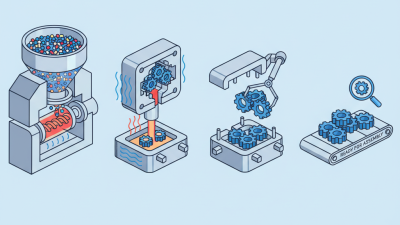
Choosing the right injection molding process begins with the part, not the machine. A thin automotive panel, a medical housing, and a small consumer cap demand different decisions. Geometry, resin behavior, wall thickness, surface finish, and tolerance requirements all influence the result. Production volume matters too. A mold for 500 parts may not justify the same investment as one for 500,000 units.
The injection molding process should be evaluated through practical manufacturing evidence. Review fill analysis, cooling performance, expected cycle time, and likely defect risks before approving tooling. Experienced engineers also compare standard injection molding with insert molding, overmolding, gas-assisted molding, or liquid silicone molding when appropriate. Material suppliers and qualified molders can provide valuable data, but their recommendations should be checked against your drawings and production goals. Small details matter. A sharp internal corner can create stress. An uneven wall can cause sink marks or warpage.
There is no universal best method. That is easy to say, but often ignored. Early cost estimates may change after mold-flow analysis or prototype testing. A cheaper tool can create higher scrap, slower cycles, or difficult maintenance later. Reliable selection balances part performance, tooling cost, manufacturing stability, operator capability, and regulatory expectations for the intended industry. This guide explains how to compare these factors clearly, identify hidden trade-offs, and choose a process that remains practical beyond the first production run. Some assumptions will be wrong. Recheck them before committing.
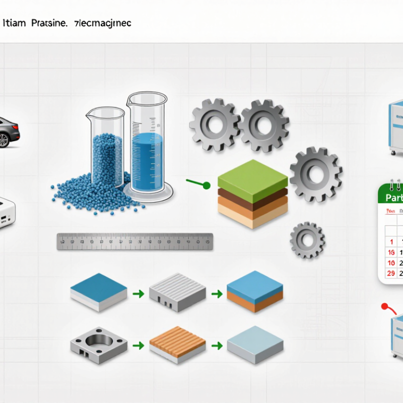
Start with the part, not the machine. Record its dimensions, wall thickness, tolerance, surface finish, and expected environment. A thin, ribbed enclosure may need different flow and cooling considerations than a thick, load-bearing component. List the resin family and any inserts, colors, or soft-touch features. These details can point toward standard molding, insert molding, or overmolding. They also reveal where a design may be difficult to fill or eject.
Set a realistic production target. Estimate annual demand, batch size, launch timing, and expected product life. A short run may not justify a complex, multi-cavity tool, even if its cycle time looks attractive. Conversely, high demand can make cavity count, automation, and tool maintenance central cost drivers. PlasticsEurope’s industry report Plastics – the Fast Facts 2024 estimates global plastics production at 413.8 million tonnes in 2023. That scale makes material choice consequential, but it does not determine the right process for an individual part. The part’s actual requirements must lead.
Put numbers beside the trade-offs: target unit cost, acceptable scrap, dimensional variation, and required output per shift. Ask a mold maker to review fill, cooling, and ejection risks before locking the design. A simple prototype or mold-flow study can expose thin-wall hesitation or uneven cooling. These early estimates are rarely perfect. Revisit them when testing reveals a mismatch between the drawing and the molded part.
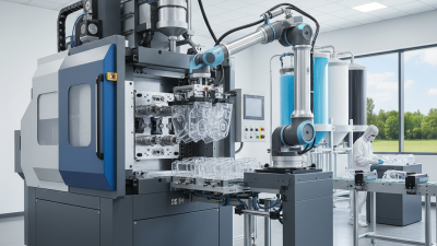
Choosing an injection molding process starts with the material and the part, not the machine. A thin-walled polypropylene cover may suit conventional injection molding because the resin flows readily into narrow sections. A thick, solid component is different. Its center can cool slowly, leaving sink marks or internal stress. Adding ribs and keeping wall thickness more even can improve results, though the design may need revision.
Material behavior matters. Glass-filled nylon can provide stiffness, but its fibers may create visible flow patterns and affect strength across weld lines. Flexible elastomers often need careful control of temperature and injection speed. For very small, detailed parts, micro-injection molding may be worth evaluating; larger parts may call for structural foam molding to reduce weight. Not every process fits every geometry.
Check the details. A sharp corner can concentrate stress, while a deep, narrow feature may complicate mold filling and part release. Draft angles help parts leave the mold cleanly, but they can alter a precise surface or dimension. Prototype samples reveal issues that drawings may miss. I have seen teams overvalue a polished surface and overlook how a gate mark lands on the finished part. That choice deserves another look. When comparing methods, ask a molder to review resin data, wall sections, tolerances, expected volume, and cosmetic requirements together. A process that looks efficient on paper may not be stable in production.
How to Choose the Right Injection Molding Process?
Compare process options, tooling needs, and equipment before requesting a quote. Standard injection molding suits repeatable, high-volume parts, while insert molding can combine plastic with metal components in one cycle. Overmolding adds a second material, but requires precise part handling and compatible materials. These options affect cycle time, part design, and tooling complexity. A Grand View Research market report estimated the global injection-molded plastics market at USD 330.4 billion in 2023. That figure signals a large, varied field—not a reason to choose the most complex process.
Tooling decisions can reshape the economics. A single-cavity mold may cost less and simplify early trials, while a multi-cavity tool can increase output once demand is steady. Cold runners leave material in the runner system; hot runners reduce that waste but add heated components and maintenance needs. Details matter. A narrow gate or thin wall can demand higher injection pressure and more capable equipment. Match machine clamp force, shot capacity, and platen size to the mold, not just the part’s weight. MarketsandMarkets projected the injection molding market would grow from USD 284.6 billion in 2023 to USD 361.9 billion by 2028. Those estimates describe market growth, not process suitability. Honestly, early tooling quotes can still miss the cost of revisions. Share expected volumes, resin, tolerances, and surface finish with the molder, then review a sample part and cycle assumptions before committing.
Compare typical cycle time, tooling lead time, and equipment complexity across common injection molding process options.
Conventional single-shot molding generally offers the simplest equipment and shortest tooling path. Insert molding and overmolding can improve product functionality but require additional handling, tooling features, or secondary material systems. Gas-assisted molding may reduce sink marks and material usage, but it typically requires the highest equipment and process-control investment. Values shown are representative industry midpoints; actual results vary by part geometry, resin, mold design, production volume, and automation level.
Production volume should guide the process before equipment selection begins. Low-volume projects may justify simpler tooling, shorter runs, or rapid mold fabrication. These options reduce initial spending, but they can increase part variation. That trade-off is easy to underestimate. For several thousand parts, a durable steel mold may provide better cost control. Its higher upfront price becomes less significant as cycle counts rise. Always calculate tooling, material, labor, maintenance, and scrap costs together.
Quality requirements must remain measurable. Define acceptable tolerances, surface texture, color consistency, and strength before requesting quotations. A process that produces clean parts at 20 seconds per cycle may still fail if warping reaches a sealing surface. Mold temperature, injection speed, cooling time, and material moisture can affect every batch. Small details matter. Inspect early samples with gauges and visual standards, not assumptions. A spreadsheet may predict a low unit cost, but real production can expose hidden adjustments.
Experienced teams also review part geometry before choosing the process. Thick walls may cause sink marks, while sharp corners can increase stress and tooling difficulty. Design changes are often cheaper before mold construction. However, teams sometimes overengineer early prototypes and waste money on unnecessary precision. That mistake deserves honest review. Select the simplest process that meets volume, cost, and quality targets, then verify it through a controlled trial.
Selecting an injection molding process should begin with physical evidence, not a supplier’s promise. Build a prototype that matches the intended resin, wall thickness, and cooling conditions. Then test it under realistic loads, temperatures, and assembly forces. A glossy prototype can still mislead.
The 2024 Wohlers Report valued global additive manufacturing at about 20 billion dollars in 2023. This growth makes printed prototypes useful for checking fit before cutting steel. However, printed parts may hide shrinkage, weld-line weakness, and surface differences found in molded components. Use prototypes for geometry. Use test molds for process decisions.
Measure fill time, cavity pressure, cooling time, part weight, and dimensional change. Follow ISO 294-1 for molding test conditions where applicable. For tensile checks, ASTM D638 provides a repeatable method. Compare results across at least three molding cycles. One successful shot proves very little.
A practical trial should include thin ribs, bosses, snap-fits, and visible surfaces. Record short shots, flash, sink marks, warpage, and ejection damage. The 2023 Grand View Research market analysis estimated continued growth in injection molding demand, increasing pressure for stable, repeatable production. Yet market growth does not guarantee your design will mold cleanly. Our first settings are often wrong. That is useful. Review the failure, adjust one variable, and test again.
| Validation Route | Best For | What It Can Validate | Key Tests and Checks | Important Limitations | Suitable Next Step |
|---|---|---|---|---|---|
| 3D-printed prototype | Early design reviews, ergonomic assessment, fit checks, and assembly studies. | Overall form, approximate dimensions, access for assembly, and potential interference with neighboring parts. | Measure critical dimensions; check mating parts and clearances; inspect handling and assembly sequence. | Printed parts do not reproduce injection-molding flow, weld lines, molded surface finish, or the properties of the intended molded resin. | Revise the design, then machine a prototype or build prototype tooling when molded-part behavior matters. |
| CNC-machined prototype | Functional evaluation when a part is needed in a specified material or with tighter dimensional control than a visual model. | Fit, selected mechanical properties of the machined material, and performance of critical features. | Inspect critical dimensions; test assembly, loading, sealing, or other requirements defined for the part. | Machining starts from stock and does not reproduce molding-related shrinkage, gate effects, fiber orientation, or molded surface characteristics. | Use prototype injection tooling if performance depends on the molding process or molded resin behavior. |
| Prototype injection tooling | Checking a design and molding setup with injection-molded samples before committing to production tooling. | Part fill, ejection, molded dimensions, surface appearance, and suitability of the selected resin under trial conditions. | Record material and machine settings; inspect dimensions and appearance; check for short shots, flash, sink marks, warpage, and ejection problems. | Prototype tools and trial conditions may differ from production tooling and validated mass-production conditions. | Update the part or process, then confirm the final design and production tooling with documented trials. |
| Production-tooling trial | Confirming the production mold, material, and process settings before routine manufacturing. | Repeatability of molded parts, dimensional capability for specified features, cycle stability, and readiness of inspection methods. | Run consecutive shots under recorded conditions; measure critical-to-quality dimensions; review defects, cycle data, and part-to-part variation. | Results apply to the tested combination of tool, machine, resin, settings, and inspection method; changes may require revalidation. | Approve documented process settings and quality checks before production release. |
| Selection principle: Choose the least costly validation route that can answer the current design or process question. Confirm requirements, sample size, acceptance limits, and test methods with the project team; validation results depend on the part, resin, tooling, and intended application. | |||||