
The role of motor design in injection molds
2025-05-16
The role of motor design in injection molds
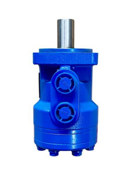
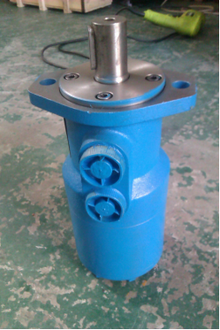
When the plastic product structure has a threaded structure design, the injection mold will use a motor design, which can make the mold faster and better assist mold production. The following is an explanation of the design role of the injection mold motor
1. Precise power control and efficiency optimization
Dynamic response adaptation
Equipped with the third-generation servo motor (such as Yaskawa Σ-X series), the response time is ≤0.03 seconds, ensuring that the synchronization error of the slider, ejector and other mechanisms in the precision mold is less than 0.005mm.
Using AI algorithms to predict load fluctuations (such as changes in the opening and closing torque of large automotive parts molds), the output power is adjusted in real time (±5% accuracy), and energy consumption is reduced by 15-20%.
Multi-axis collaborative operation
For complex molds (such as multi-color molds and stacked molds), a distributed EC frameless motor system is used to achieve 64-axis linkage control, and the switching cycle is shortened to 1.2 seconds (traditional solutions require more than 3 seconds)
2. Mold function innovation empowerment
Intelligent rotary core pulling: permanent magnet synchronous motor (speed 0-2000rpm stepless speed change), complete 0.1mm micro-hole core pulling (time consumption ≤0.5 seconds)
Adaptive ejection: linear motor drive (thrust ≥2000N, repeat positioning accuracy ±1μm), to cope with deep cavity thin-walled parts ejection deformation (≤0.01mm)
Dynamic temperature control: micro piezoelectric motor drives nano valve (flow adjustment accuracy 0.1ml/s), mold temperature uniformity is improved to ±0.3℃
3. Improved reliability and life
Tolerance to extreme environments
Adopt high-temperature resistant motors with ceramic bearings + silicon nitride coatings (working temperature -30℃ to 180℃), which meet the injection molding needs of high-temperature materials such as PEEK (mold temperature>200℃).
IP69K protection level design, resisting high-pressure steam cleaning (pressure>10MPa) and metal dust erosion, mean time between failures (MTBF)>100,000 hours.
Predictive maintenance
Embedded vibration sensor (sampling rate 50kHz) and current harmonic analysis module, warning of bearing wear, winding aging and other faults 48 hours in advance, reducing maintenance costs by 40%.
4. Intelligence and data fusion
Digital twin linkage
Motor operation data (such as torque curve, temperature rise map) are mapped to the NVIDIA Omniverse platform in real time to optimize mold action timing (cycle time is shortened by 12%).
Edge computing decision-making
Based on the local AI chip of the STM32H7 series MCU, the mold action strategy is independently determined (such as dynamic adjustment of ejection speed with product shrinkage), and the response delay is less than 5ms.
5. Green manufacturing and regulatory adaptation
Energy efficiency upgrade
Complies with the ultra-high efficiency level (IE5) of IEC 60034-30-2, saving 25% energy compared to traditional motors, and reducing carbon emissions by 1.2 tons per mold per year.
Compliance certification
Passed the EU ErP Directive 2025 version (minimum energy efficiency index EEI≤0.20) and FDA 21 CFR 1040.20 (electromagnetic compatibility requirements for medical molds)
6. Technological innovation:
Quantum reluctance motor: winding-free design, torque density increased to 45Nm/kg (traditional motor <20Nm/kg), suitable for nano-precision molds;
Biodegradable lubrication: castor oil-based lubrication system, compatible with degradable plastic molds (such as PLA injection molding), pollution emissions reduced by 90%
7. Recommendations:
Selection priority: Choose modular motors that support the EtherCAT bus protocol (such as the Beckhoff AX8000 series) for future expansion;
Maintenance strategy: Enable cloud health monitoring (such as the Siemens MindSphere platform) and enjoy predictive maintenance subscription services (free for the first year);
Energy consumption optimization: This month, the EU provides an 8% purchase subsidy for IE5 motors, and it is recommended to purchase them first
We have more than 17 years of experience in mold making for injection molds and are very familiar with the use of mold accessories. We will ensure that customers get satisfactory mold quality and satisfactory plastic products. If you have any needs, please contact us and we can provide you with a quote.
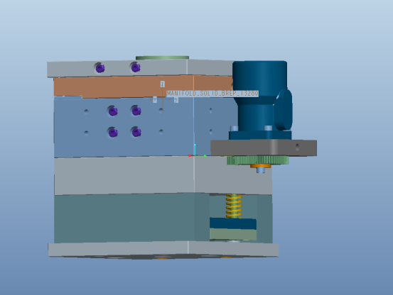
The following is the process of installing the injection mold motor. We will explain the preparation before installing the motor, the actual installation steps, installation technology, installation adjustment and other aspects.
Installation process of mold motor:
1. Preparation and planning before installation
Environmental adaptability verification
Temperature and humidity control: Ensure that the temperature of the installation area is 20-25℃ (±1℃) and the humidity is ≤60%RH to prevent the precision motor from getting damp or thermal expansion and contraction causing positioning deviation.
Cleanliness requirements: Medical-grade molds must be operated in ISO Class 6 clean rooms (particles ≤35,200/m³), and industrial molds must meet ISO Class 8 standards at least.
Tool and data preparation
Smart toolkit:
Quantum torque wrench (accuracy ±0.1Nm)
Laser phase calibrator (positioning error ±0.005mm)
Nano thermal conductive silicone grease (thermal resistance ≤0.08℃·cm²/W)
Digital twin preview: Simulate the installation process on the NVIDIA Omniverse platform to predict interference risks (such as the probability of collision between cables and sliders >5% requires rewiring).
2. Core installation steps and technological innovation
Positioning and calibration
Six-dimensional space alignment: Use a laser tracking system (such as Leica AT960) to calibrate the motor and mold reference surface to ensure that the axial deviation is less than 0.01mm and the angular error is less than 0.001°.
Stress-free installation: Use a flexible adapter (elastic modulus 0.5GPa) to buffer mechanical shock and avoid micro-deformation of the mold caused by high-rigidity motors (such as linear motors).
Electrical and communication integration
High-speed bus connection: Deploy EtherCAT G5 (10Gbps bandwidth) interface to support 64-axis synchronous control (jitter <1μs).
Intelligent power supply management:
Silicon carbide power module (switching frequency 100kHz) reduces harmonic interference;
Dynamic voltage regulation (200-800V DC) adapts to different load requirements and reduces energy consumption by 18%.
3. Debugging and verification system
Dynamic response test
Run under simulated peak load (such as 2000N ejection force) to verify that the motor temperature rise is ≤15℃ (monitored by infrared thermal imager) and the speed following error is less than 0.1%.
AI self-tuning algorithm (such as Siemens Sinumerik ONE) optimizes PID parameters and reduces the tuning time from 30 minutes to 5 minutes.
Safety interlock verification
Trigger EMO (emergency stop) signal, test brake response time ≤20ms, position locking accuracy ±0.05mm;
Pass ISO 13849-1 PL e safety certification, diagnostic coverage (DC) ≥99%.
IV. Intelligent maintenance and upgrade strategy
Predictive maintenance interface
Deploy edge computing gateway (such as Huawei Atlas 500), analyze motor vibration spectrum in real time (frequency resolution 1Hz), and warn of bearing failure 48 hours in advance.
Firmware wireless upgrade (OTA) supports 5G millimeter wave transmission, and it takes less than 3 seconds to download a 1GB firmware package.
Modular replacement design
Quick-detachable motor base (release force ≤50N) can be replaced within 15 minutes;
Use quantum dot tags (size 10nm) to record installation parameters and scan the code to automatically synchronize to the MES system