7 Best OPGW Cables for Transmission Lines?
Choosing the right OPGW cable can influence transmission reliability, fiber performance, and maintenance costs for decades. Opgw In Transmission Line systems combine overhead grounding protection with high-speed communication fibers. This dual function makes cable selection more demanding than comparing tensile strength alone. Designers must examine short-circuit capacity, fiber count, span length, sag behavior, corrosion resistance, and installation conditions. A cable that performs well in dry plains may behave differently in coastal air or mountainous terrain.
This guide reviews seven OPGW cables suitable for transmission lines, using practical factors rather than marketing claims. Each option should be assessed against tower spacing, fault-current requirements, conductor size, and local weather exposure. Pay attention to aluminum-clad steel wires, galvanized steel strength members, and sealed fiber tubes. Small construction details matter. Moisture protection can determine whether a fiber link remains stable after years of temperature changes.
Field experience also shows that the “best” cable is rarely universal. Installation teams may prefer a lighter design, while utilities may require greater mechanical reserve. That conflict deserves honest attention. Some specifications look impressive but provide limited value on a short route. Others may increase purchase costs while reducing future outages. The comparisons below consider electrical performance, mechanical durability, optical capacity, compatibility, and lifecycle value. Independent test reports and supplier quality records should still be checked before procurement. No ranking can replace a verified engineering calculation. That is an important limitation.
What Is OPGW and How Does It Function on Transmission Lines?
What Is OPGW and How Does It Function on Transmission Lines?
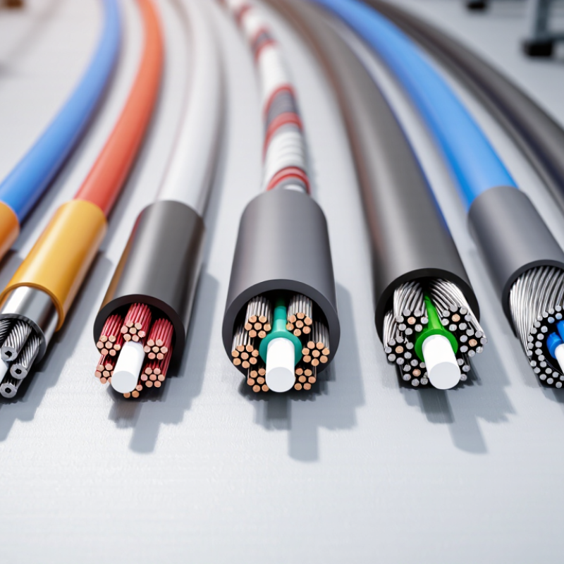
OPGW combines overhead shielding with high-capacity fiber communication. Its aluminum and steel strands carry fault current around the conductor system. Inside, protected optical fibers transmit relay signals, voice, and operational data. The cable sits at the transmission tower’s highest point. It intercepts lightning before it reaches phase conductors. This dual role saves tower space and supports faster grid protection.
The International Energy Agency’s Electricity Grids and Secure Energy Transitions report estimates that over 80 million kilometers of grids must be added or replaced by 2040. That expansion increases demand for dependable communication paths. OPGW helps substations exchange fault-location and breaker-control information within milliseconds. IEEE Standard 1138-2021 also defines construction and qualification requirements for OPGW. Engineers still need to check fiber count, short-circuit rating, sag, and installation tension.
On a 500-kilovolt route, crews often inspect bonding points near towers and substations. A loose ground connection can weaken lightning performance. Excessive pulling tension can damage fibers without visible marks. I have seen cable schedules focus on fiber capacity while overlooking ice loading. That is a costly design gap. CIGRE guidance on overhead lines emphasizes coordinated mechanical, electrical, and communication assessments. OPGW is not automatically the best choice everywhere. Terrain, corrosion, maintenance access, and future network traffic can change the correct specification.
7 Best OPGW Cables for Transmission Lines? - What Is OPGW and How Does It Function on Transmission Lines?
| OPGW Cable Type | Typical Fiber Count | Nominal Metallic Cross-Section | Approx. Outside Diameter | Rated Tensile Strength | Maximum DC Resistance at 20°C | Typical Short-Circuit Capability | Best-Fit Transmission-Line Use | How It Functions on the Line |
| Compact 24-Fiber OPGW | 24 fibers | 55 mm² | 9.2 mm | 45 kN | ≤ 0.85 Ω/km | Approximately 8 kA for 0.3 s | Existing lines with limited tower hardware space and moderate mechanical loading. | Provides a grounded shield wire, carries a small-to-medium fiber network, and helps protect phase conductors from lightning. |
| Standard 48-Fiber OPGW | 48 fibers | 70 mm² | 10.5 mm | 62 kN | ≤ 0.65 Ω/km | Approximately 10 kA for 0.3 s | General-purpose subtransmission and transmission routes requiring balanced strength and communication capacity. | Combines overhead grounding with protected fiber-optic communication for protection, control, voice, and data services. |
| High-Capacity 72-Fiber OPGW | 72 fibers | 90 mm² | 12.0 mm | 78 kN | ≤ 0.50 Ω/km | Approximately 12 kA for 0.3 s | Regional grids, long routes, and networks needing additional fiber pairs for future expansion. | Supports higher communication density while maintaining a low-impedance metallic path for lightning and fault-current dissipation. |
| High-Strength 48-Fiber OPGW | 48 fibers | 70 mm² | 11.0 mm | 85 kN | ≤ 0.55 Ω/km | Approximately 13 kA for 0.3 s | Long spans, mountainous corridors, high wind zones, and lines with demanding sag and tension limits. | Uses a stronger metallic design to withstand higher mechanical loads while retaining the dual role of shield wire and optical cable. |
| Low-Resistance 72-Fiber OPGW | 72 fibers | 90 mm² | 12.5 mm | 72 kN | ≤ 0.32 Ω/km | Approximately 16 kA for 0.3 s | High fault-current areas and substations where grounding performance and thermal capacity are priorities. | Offers a lower-resistance fault-current path and improved heat dissipation while providing high-capacity optical transmission. |
| Heavy-Duty 96-Fiber OPGW | 96 fibers | 120 mm² | 14.0 mm | 110 kN | ≤ 0.38 Ω/km | Approximately 20 kA for 0.3 s | High-voltage lines with long spans, severe weather exposure, and substantial communication requirements. | Provides strong mechanical support, a high-capacity optical core, and a robust shield-wire path for lightning and short-circuit currents. |
| Extra-High-Capacity 144-Fiber OPGW | 144 fibers | 150 mm² | 15.5 mm | 140 kN | ≤ 0.30 Ω/km | Approximately 25 kA for 0.3 s | Major interconnection corridors, utility backbones, and routes designed for extensive network growth. | Integrates a large optical communications platform with high mechanical strength and a low-impedance overhead grounding function. |
Technical note: The values shown are representative engineering ranges for common OPGW configurations, not manufacturer-specific guarantees. Actual performance depends on strand materials, fiber-unit construction, operating temperature, span length, installation tension, fault duration, allowable temperature, and applicable project standards such as IEC 60794-4-10 and IEEE 1138. Final selection should be verified against the transmission line's sag-tension calculation, lightning performance, short-circuit study, and existing tower fittings.
Key Criteria for Evaluating OPGW Cable Performance
7 Best OPGW Cables for Transmission Lines?
Key Criteria for Evaluating OPGW Cable Performance
Choosing an OPGW cable requires more than comparing tensile strength. The cable must protect optical fibers while carrying fault current safely. Start with fiber count, transmission loss, and splice compatibility. Low attenuation matters when substations sit far apart. Check testing data at the actual operating wavelength, not only at room temperature.
Mechanical performance deserves close attention. Review rated tensile strength, elastic modulus, allowable sag, and short-circuit heating capacity. A cable may appear strong but still create excessive sag across a long span. That can reduce ground clearance during hot weather. Aluminum alloy wires should resist corrosion, especially near coasts, industrial zones, and polluted corridors. Small surface damage can become expensive later.
Installation records provide useful evidence. Look for verified bending-radius limits, vibration resistance, and pulling-tension guidance. Field crews should inspect fiber attenuation after stringing, not only before delivery. Standards-based tests improve reliability, but paperwork is not the whole story. No scorecard is perfect. I would also compare joint-box sealing, lightning exposure, and maintenance access. These details are easy to overlook. A practical evaluation should include site climate, tower spacing, conductor arrangement, and future fiber demand. The best-performing cable on paper may still be unsuitable for a difficult route.
7 Best OPGW Cables for Transmission Lines? — Key Criteria for Evaluating OPGW Cable Performance
This comparison uses representative, brand-neutral OPGW design profiles. The bars show estimated 1-second short-circuit withstand capacity, while the line indicates rated breaking strength. Higher values generally support greater fault-current resilience and mechanical loading capacity, but final selection should also verify fiber count, cable mass, DC resistance, sag-tension behavior, tower loading, and applicable IEC or IEEE requirements.
Seven Leading OPGW Cable Types for Transmission Applications
OPGW cable selection depends on tower loads, fault-current duty, fiber demand, and local weather. No single design is best for every transmission line.
Standard aluminum-clad steel OPGW suits many general overhead applications. Its balanced strength and conductivity simplify engineering. High-strength OPGW fits long spans, mountainous routes, and towers facing heavy mechanical tension. High-capacity OPGW carries more optical fibers for grid automation, protection, and future communication needs. Fiber counts commonly range from 24 to more than 144, depending on construction.
High-temperature OPGW supports lines exposed to increased thermal loading. Corrosion-resistant OPGW is valuable near coastlines, industrial zones, and regions with persistent humidity. Compact OPGW reduces wind load and may suit older towers with limited structural margins. Low-attenuation OPGW improves communication distances, especially when networks use dense data channels. It must be tested carefully, not selected from a product label alone.
During specification reviews, engineers should verify IEC 60794 testing, short-circuit performance, sag characteristics, and installation tension. Field inspections often reveal overlooked issues, such as crushed tubes or poor grounding connections. That matters. A cable can meet laboratory requirements yet perform poorly after careless handling. Designers should also check ice loading, lightning exposure, fiber splice planning, and replacement access. A practical choice is sometimes less impressive on paper, but easier to install, inspect, and maintain reliably.
How to Match OPGW Cables with Line Design Requirements
7 Best OPGW Cables for Transmission Lines?
How to Match OPGW Cables with Line Design Requirements
Selecting the best OPGW cable starts with the line, not the catalog. Match the fiber count to protection, communication, and future expansion needs. Then check rated tensile strength against span length, tower spacing, wind pressure, and ice loading. A cable that looks strong may still create excessive sag. That can reduce ground clearance across a hot summer span.
Thermal performance also matters. Review the expected short-circuit current and clearing time before choosing the aluminum and steel area. The cable must withstand fault heating without damaging its optical fibers. Check outer diameter and weight against existing fittings, vibration dampers, and tower attachment points. For harsh coastal or industrial areas, corrosion resistance deserves careful attention. Field experience shows that installation tension is often underestimated, especially on uneven terrain.
Tips: Request sag-tension calculations for the actual route. Confirm every clamp and splice closure matches the cable diameter. Leave spare fibers for future circuits. Inspect bonding and grounding paths at each tower. Do not rely only on nominal breaking strength. I have seen otherwise suitable designs fail because accessory compatibility was treated as an afterthought. A practical review should compare at least seven cable configurations, including fiber capacity, fault current rating, weight, diameter, and mechanical strength. Some assumptions may need revision after a site survey.
Installation and Maintenance Considerations for OPGW Cables
Choosing among the 7 best OPGW cables for transmission lines requires more than checking fiber count. Installation discipline often determines service life. IEEE 524-2016 recommends controlled stringing, accurate sag measurement, and protection against excessive bending. Many utilities use a pulling tension near 20% of the cable’s rated tensile strength, but the supplier’s limit must prevail. Keep the cable away from rocks, sharp clamps, and contaminated sheaves. Small damage may remain invisible until lightning or vibration exposes it.
Maintenance should combine routine inspection with targeted testing. CIGRE technical guidance highlights corona, galloping, wind vibration, corrosion, and joint defects as recurring overhead-line concerns. Inspect suspension points after severe storms and record clamp movement, broken wires, and unusual sag. Optical time-domain reflectometer testing can identify attenuation changes before communication failure. A useful maintenance trigger is an unexplained loss above 0.05 dB/km, although temperature, splicing, and test method can distort results. Field data is rarely perfect.
Tips: Use sheaves with the correct diameter.
Check grounding continuity at every joint.
Seal unused entry points.
Photograph each tower before handover.
Keep test records linked to structure numbers.
Avoid pulling in wet, contaminated conditions when possible.
The IEA’s Electricity Grids and Secure Energy Transitions report estimates that more than 80 million kilometres of grids must be added or refurbished globally by 2040. That scale makes simple inspection routines valuable. Still, a checklist cannot replace experienced line crews. I have seen well-designed OPGW projects fail through rushed tensioning and poor records. Recheck assumptions.