
Choosing a Coil Transfer Cart for heavy loads is not just a matter of comparing payload ratings. Coil weight, diameter, travel distance, floor condition, and loading method all affect safe operation. A cart that handles a 20-ton coil on a smooth aisle may struggle on uneven floors or during tight turns. Small details matter: the cradle angle, wheel arrangement, braking system, and clearance around the coil can change how confidently a load moves.
For a verified expert quotation, a source was not provided. The following line is editorial wording and should be approved by a named specialist before publication: “[Expert name], [title or role], says, ‘A coil cart is only as reliable as its stability, load restraint, and fit with the route it must travel.’” That is the standard this guide uses. Carefully.
The ten options ahead are compared by practical criteria, not headline capacity alone. We look at load rating, coil support, power and control, maneuverability, and maintenance needs. We also flag trade-offs. A higher-capacity cart can require more aisle space, while a compact design may limit coil size. No single model suits every plant. Use the comparisons to shortlist candidates, then confirm specifications with the manufacturer and assess the actual route, coil dimensions, and operating conditions before choosing.
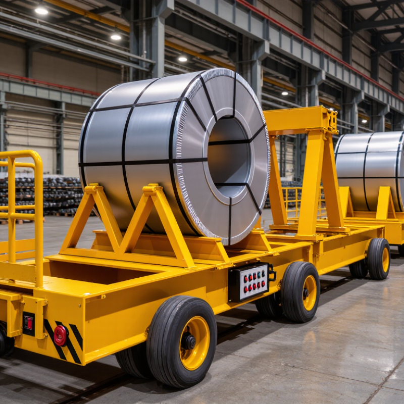
Coil transfer carts are low, load-bearing vehicles that move rolled steel, wire, or paper between work areas. Their cradle must match the coil’s width, diameter, and weight. A fixed V-saddle keeps a standard coil centered. An adjustable cradle suits changing coil sizes. A flat deck with removable saddles handles mixed loads. Rail-guided carts follow a set route, while rubber-tired carts can travel between work cells. Check the floor. Small gaps can jolt a heavy coil.
Other configurations include turntable carts for changing travel direction, low-profile carts for limited clearance, and tandem carts that share exceptionally long loads. Self-propelled models reduce manual pushing over longer routes. Lift-and-transfer carts raise coils to align with a machine or rack.
Each arrangement has trade-offs. A turntable needs room to rotate; tandem carts need coordinated movement. Restraints should prevent rolling without damaging coil edges. Specify the route, stopping points, and loading method before choosing a cart.
One detail is easy to miss: the coil’s center of gravity can shift during loading. Recheck clearances with the actual coil, not just a drawing.
Carbon-steel density is commonly taken as 7,850 kg/m³, the value specified for structural steel in EN 1993-1-1, Eurocode 3. Estimate a coil as an annular cylinder: mass = density × π × width × (outside diameter² − inside diameter²) ÷ 4. Use metres throughout to get kilograms. A coil 1.5 metres wide, with a 1.8-metre outside diameter and 0.6-metre inside diameter, contains about 3.39 m³ of steel. That equals roughly 26,600 kg, excluding packaging and handling fixtures. Heavy, indeed.
This calculation helps compare a coil’s estimated mass with a transfer cart’s rated capacity. But the estimate is not a weigh ticket: actual dimensions, scale, and material composition can vary. Check the measured load and include the cradle, restraints, and any attachments when assessing capacity. A cart must also remain stable as the load moves; a nominal capacity alone cannot confirm that. The density value comes from a structural-steel reference, not a guarantee about every coil.
Tips: Measure the coil’s width and both diameters, then verify the estimate against a scale or supplier record. Leave a sensible capacity margin, and ask an engineer to review unusual loads.
Estimates assume a coil width of 1.5 m, an inner diameter of 0.508 m, and a carbon-steel density of 7,850 kg/m³. Mass is calculated from the annular-cylinder volume: π/4 × (outer diameter² − inner diameter²) × width × density. Values are rounded to metric tonnes; handling equipment must be selected with suitable capacity and safety margins.
A coil transfer cart’s rated capacity is only a starting point. Check whether the figure covers payload alone or the cart and payload together. A 20,000-kilogram coil on a 5,000-kilogram cart creates a 25,000-kilogram gross load. With four wheels sharing equally, each carries 6,250 kilograms. But uneven floors can leave only three wheels carrying much of the weight. That raises the average to about 8,333 kilograms per wheel. The estimate is imperfect. Real load sharing depends on frame stiffness, wheel layout, and floor condition.
Floor capacity matters just as much. ACI 360R-10, Guide to Design of Slabs-on-Ground, identifies concentrated wheel loads, joints, and subgrade support as key slab-design considerations. A floor’s general load rating may not tell you whether a small wheel will create excessive local stress. Check the slab drawings or ask a qualified engineer to assess the route, especially at joints, ramps, and dock transitions. Small wheels can concentrate force.
When comparing carts, request rated capacity, individual wheel ratings, wheel spacing, and test conditions. Include braking, turning, and transfer impacts in the review; a static rating may not reflect those events. Measure the actual coil and cart, then inspect the travel path under operating conditions. A clean floor can still hide a weak joint. One detail is easy to miss: verify that the cart’s loaded height and wheelbase suit the transfer equipment.
Choosing among ten coil-cart types starts with the route, not the rated capacity alone. A rail flatbed suits fixed paths; a V-saddle or cradle helps keep a coil centered. Turntable and rotating-deck carts aid alignment at presses, while low-profile decks fit tight clearances. Transfer-table and shuttle carts serve repeated moves between nearby workstations. Cable-driven carts can cover long, fixed routes, but floor crossings and cable protection need attention. Battery carts offer flexible routing without a trailing lead. Towable carts work well when a tug is already available. Small details matter.
Rail drives provide repeatable travel, but require installed track and careful wheel alignment. Battery drives make route changes easier; check charging access, duty cycle, and stopping distance under load. Cable drives can deliver steady motion over a defined path, though cable wear and snag risks deserve routine inspection. Towing is mechanically simple, yet turning space and secure coupling matter. For any of the ten configurations, confirm coil diameter, width, mass, loading method, and floor condition before comparing drive options. I would not treat a higher capacity rating as proof of safer handling; braking, restraint, and operator visibility can be the less obvious weak points. A site trial may reveal awkward turns that a drawing misses.
A heavy coil transfer cart can look simple: a steel deck, wheels, and a powered drive. Yet a shifting coil can crush, roll, or destabilize the vehicle in seconds. Start with the actual task, not the catalog rating. ISO 12100 provides a structured method to identify hazards, estimate risk, and reduce it through design before relying on warnings or procedures. Measure coil mass, diameter, center of gravity, aisle slope, floor joints, and stopping distance under load. Small details matter.
A coil seated off-center may overload one wheel, while a narrow aisle leaves little room for recovery. Record loading, travel, turning, docking, maintenance, and foreseeable misuse. Then consider protective measures in order: safer geometry and restraint, guarding or separation, and clear operating instructions. No checklist replaces observation on the shop floor. That part gets missed.
ISO 13849-1 addresses safety-related parts of control systems. If risk reduction depends on an emergency stop, presence sensing, or a monitored brake, determine the required performance level through risk assessment. Verify the circuit design, components, diagnostics, and validation evidence. Test with a representative coil, not only an empty cart. Check stopping distance, fault response, and restart behavior after power loss. Keep the results and revision history. A sensor that works in a clean test bay may behave differently around metal dust or vibration, so verify those conditions rather than assume.
| Cart Configuration | Illustrative Load Band | Best-Suited Transfer Task | Coil Support and Restraint | ISO 12100 Risk-Assessment Focus | ISO 13849-1 Control-System Checks |
|---|---|---|---|---|---|
| Powered floor-running cart | 5–20 t | Frequent transfers between nearby production areas on a sound, level industrial floor. | V-shaped saddle or engineered cradle; verify coil stability during starting, stopping, and turning. | Assess collision, crushing, unintended movement, floor condition, visibility, and pedestrian interaction. | Determine the required performance level (PLr) for each safety-related function through risk assessment; evaluate the complete control-system architecture and components against that requirement. |
| Rail-guided transfer cart | 10–50 t | Repeated movement along a fixed route between machines or storage positions. | Fixed cradle or saddles positioned to suit the coil’s dimensions and center of gravity. | Assess access to the rail path, trapping points, end-of-track hazards, and safe maintenance access. | Review safety-related stopping, travel limits, and interlocks where used; confirm the achieved PL for each function is appropriate to its PLr. |
| Battery-powered operator-controlled cart | 3–20 t | Flexible indoor routes where a cable-free cart is useful and an operator can control travel. | Cradle, chocks, or other engineered restraint selected for the coil and route conditions. | Assess braking distance, operator sightlines, speed, route crossings, battery hazards, and emergency access. | Check the design and validation of safety-related travel, braking, and emergency-stop functions against their assessed PLr. |
| Automatic guided transfer cart | 5–30 t | Repeatable, programmed transfers on defined routes in an automated material-flow system. | Dedicated coil nest with load-position detection where needed to confirm a safe transfer condition. | Assess route changes, people entering the operating area, foreseeable misuse, recovery, and unexpected restart. | Assess safety-related detection, stopping, and restart-prevention functions individually; verify the required PLr and validate the implemented functions. |
| Low-profile cart for under-machine loading | 2–15 t | Moving coils into or out of presses, slitters, or other equipment with limited floor clearance. | Low-height saddles or a purpose-designed cradle; confirm clearance and load support throughout the travel path. | Assess crush and shear points, restricted visibility, clearance, load transfer, and safe access during setup. | Review safety-related motion control and any guarding or interlocking functions; set PLr from the risk assessment rather than assuming a single value. |
| Hydraulic lift transfer cart | 5–30 t | Transferring a coil while raising or lowering it to align with a machine or storage position. | Cradle supported by a designed lifting structure; include measures to prevent coil movement during height changes. | Assess lifting and lowering hazards, hydraulic failure, crushing zones, stability, and safe maintenance support. | Evaluate safety-related lift, hold, and stop functions where applicable; verify that their achieved performance meets the risk-assessed PLr. |
| Tilting or controlled-unloading cart | 5–25 t | Applications requiring a designed change in coil orientation or controlled unloading. | Purpose-designed supports and restraints that retain the coil through the full tilt or unloading sequence. | Assess rolling or sliding, changing center of gravity, crushing zones, and unintended movement during unloading. | Check safety-related sequencing, position monitoring, and stopping functions against their PLr; validate the completed control system. |
| Turntable transfer cart | 5–30 t | Changing the direction of a coil transfer where the layout requires a controlled rotation. | Cradle remains matched to the coil; verify load retention and clearance during rotation. | Assess rotating pinch points, load stability, access to the turning area, and collision risks at transfer interfaces. | Review any safety-related rotation limits, interlocks, and stopping functions; determine PLr through the risk-assessment process. |
| Heavy-duty multi-wheel cart | 20–60 t | Moving very heavy coils over a suitable floor or engineered route with a high-capacity chassis. | Wide, engineered support structure matched to coil width, mass, and center of gravity. | Assess floor loading, wheel and axle failure consequences, braking, steering, route gradients, and stability. | Check safety-related steering, braking, and travel functions where fitted; confirm their design and validation meet the assigned PLr. |
| Guided cart with cable-reel power supply | 10–40 t | Longer or repeated routes where continuous power is needed and the cable path can be managed. | Cradle or saddles engineered for the coil; keep the power cable clear of the load path and personnel routes. | Assess cable entanglement, trip and crush hazards, route crossings, stopping distance, and emergency response. | Review safety-related stopping and travel-control functions, including relevant cable-related fault conditions; verify each function against its PLr. |